
But what is it ?
No it’s not for a bicycle. No it’s not for a tank.
This is made for the proud users of a DIY 3D printer or a CNC.
This is a cable trunking chain; it is meant to hold a couple of cables and move them along with the X,Y or Z axis while keeping them out of the way of the mechanical parts.
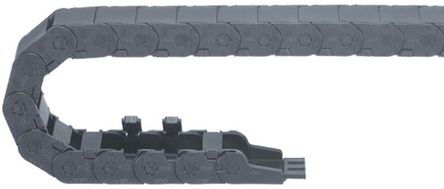
Credits: RS components
All respectable DIY machine should have some of these 🙂
Even if they are not that expensive, they still represent “nice to have” features that will not fit into a tight budget.
This tutorial explains how to build them using a Laser cutter or… a 3D printer, but it will be much slower.
Adjust the dimensions
Using the OpenSCAD model, you’ll have to adjust the dimensions to fit the side of your cable/connector.
The cables must be freely passing through the internal opening of the chain.
- Adjust parameter
Wfor the width, andHfor the height. - For the laser-cut model
- set
LCtotrue - set also the thickness
Tof your material, in mm.
- set
- For the 3D printed model
- set
LCtofalse
- set
- Press
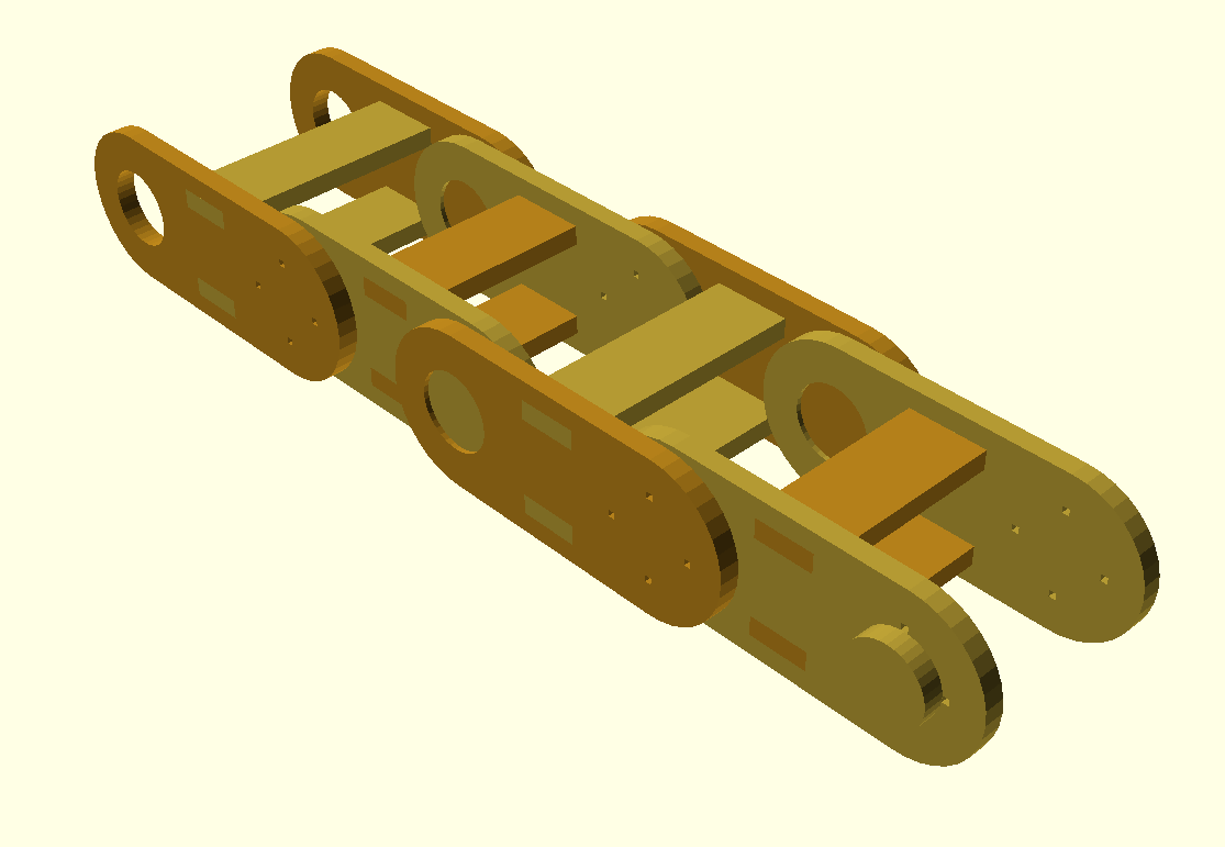
F5first for an overview. That will generate one inner link, and one outer link; they only differ by their width. - Press
F6to generate the final build.
Laser cut
Cut
File/Export the drawing to a DXF file… or your preferred 2D format.
Feed this file to your laser-cutter, cut as many as you need.
Assemble
You’ll need some kind of glue for this. My preference goes for hot glue, as this is easy and solidifies quickly. However, it is a bit bulckier and generates some glue hairs.
Start with and inner link
OpenSCAD file
// laser cut model ?
LC = false;  // or true

$fn = 36;

// link step
S = 36;

// link width
W = 40;

// thickness
T = 3;

module link()
{
    difference()
    {
        hull()
        {
            translate([ S/2,0]) circle(r=S/3);
            translate([-S/2,0]) circle(r=S/3);
        }
        translate([-S/2,0]) circle(r=S/6);
        // centering marks
        translate([S/2,0])
            for (i=[0:3])
                rotate(90*i) translate([S/6,-1/2]) square(1);
        // assembly slots for spacer
        translate([-S/8,S/3-2*T]) square([S/4,T]);
        translate([-S/8,-S/3+T]) square([S/4,T]);
    }
}

module spacer(L)
{
    translate([-S/8,0]) square([S/4,L]);
    translate([-S/6,T]) square([S/3,L-2*T]);
}

module long_spacer()
{
    spacer(W);
}

module short_spacer()
{
    spacer(W-2*T-T/2);
}

module flat()
{
    link();
    translate([0,S]) link();
    translate([1.5*S,0])    long_spacer();
    translate([2*S,0])    short_spacer();
}

module link_element_3D()
{
    linear_extrude(T) link();
    translate([S/2,0,T]) cylinder(r=S/6,h=T);
}

module big_link_3D()
{
    color([0.7,0.5,0.1])
    {
        translate([0,0,0]) rotate([-90,0,0]) link_element_3D();
        translate([0,W,0]) rotate([90,0,0]) link_element_3D();
    }
    color([0.7,0.6,0.2])
    {
        translate([0,0,-S/3+T  ]) linear_extrude(T) long_spacer();
        translate([0,0, S/3-2*T]) linear_extrude(T) long_spacer();
    }
}

module small_link_3D()
{
    color([0.7,0.6,0.2])
    {
        translate([0,T,0]) rotate([90,0,0]) link_element_3D();
        translate([0,W-2*T-T/2-T,0]) rotate([-90,0,0]) link_element_3D();
    }
    color([0.7,0.5,0.1])
    {
        translate([0,0,-S/3+T  ]) linear_extrude(T) short_spacer();
        translate([0,0, S/3-2*T]) linear_extrude(T) short_spacer();
    }
}

module model_3D(N)
{
    for (i=[0:N-1])
        translate([2*S*i,0,0])
        {
            big_link_3D();
            translate([S,T+T/4,0]) small_link_3D();
        }
}

if (LC)
    model_3D(2);
else
    flat();